
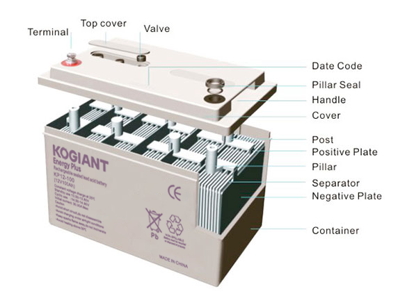
1. Battery Contruction
2.Sealing Principle
The charge/discharge reaction of the VRLA battery can be expressed by the following reaction:
Anode | Electrolyte | Cathode | Discharge | Anode | Electrolyte | Cathode | ||||||
PbO2 | + | 2H2SO4 | + | Pb | + | ® | + | PbSO4 | + | H2O | + | PbSO4 |
Lead dioxide | Sulfuric acid | Sponge lead | Charge | Lead sulfate | Water | Lead sulfate |
Overcharging causes electrolysis of the water content of the electrolyte, which generates O2 gas at the positive plate and H2 gas at the negative plate. These gasses are then discharged to the outside. Since a drop in the electrolyte levels results, adding water is occasionally needed.
The VRLA battery is designed so that the negative plate does not have to be fully charged even when the positive plate is fully charged. Furthermore, no H2 gas is generated from the negative plate although O2 gas is being generated from the overcharged positive plate. O2 generated from the positive plate then reacts with the charged sponge lead (Pb) of the negative plate and turns into lead monoxide (PbO). The lead monoxide, in turn, reacts with sulfuric acid (H2SO4) in the electrolyte to turn into lead sulfate (PbSO4), allowing the negative plate to discharge. In other words, O2 from the positive plate is absorbed by the negative plate without being expelled to the outside. Since the negative plate develops discharging with the help of O2, there always exists a portion free from discharging. As a result, the negative plate never generates H2. This completely prevents the loss of water.
The sealing principle of a VRLA battery may be expressed by the following equation
(See Figure 2 for illustration):
Negative plate (charged) | O2 gas generated from the positive plate | Negative plate | |||
Pb | + | ½ O2 | ® | (PbO) | |
Sponge lead | Oxygen gas | Lead oxide | |||
for Electrolyte | Negative plate | Electrolyte | ¯ | ||
H2O | + | PbSO4 ¬ | H2SO4 | + | (PbO) |
Water | Lead sulfate | Sulfuric acid | |||
Figure 2: Illustration of Sealing Principles
CAUTION: ALWAYS USE A BATTERY BEST DESIGNED FOR THE APPLICATION.
This guide is focused on Industrial Standby applications and NOT Automotive or Traction use.
3.Battery Features
Features of VRLA Battery
1. Non spillable
The VRLA battery uses an absorbed electrolyte system. All of the electrolyte is absorbed into the positive plates, negative plates, and the separators. Coupled with the use of special sealing epoxies, and long sealing paths for posts, VRLA batteries have exceptional leak resistance, and can be used in any position,but Cannot be inverted for use
2.Sealed and Maintenance-free Operation
There is no corrosive gas generation during normal use and no need to check the specific gravity of the electrolyte or to add water during the service life.
3. High Quality and High Reliability
The VRLA battery has stable and reliable capacity. The battery can withstand overcharge, over discharge, vibration, and shock. To assure this high quality and reliability, the batteries are 100% tested on production line for voltage, capacity, seals and the safety valve are 100% visually inspected before the final assembly process.
4. Exceptional Deep Discharge Recovery
VRLA batteries have exceptional deep discharge recovery and charge acceptance, even after deep or prolonged discharge.
3.5 Low Self-discharge
Because of the use of lead calcium grids alloy and highly purity materials. The VRLA battery can be stored long periods of time without recharge(within 6 months). The rate of VRLA battery self-discharge on open circuit is less than 2% per month at 20℃/68°F to 25℃/77°F.
5. Long Service Life
The VRLA battery has long life in standby or cyclic service.
6. Solid Copper Terminals
Ensures highest current carrying capability.
7. Tank-formed Plates
The initial capacity will be 100% and optimize cell voltage balance, due to the tank formation of the plates.
8. Computer-aided Design and Manufacturing
Ensures quality products through control of processes and standards.
4. Battery Life
Battery life depends on a number of key factors. These include:
Operating temperature of the battery;
Method of charging utilized;
Actual use of the product i.e.: standby or cycle service etc.
A. Cyclic Life
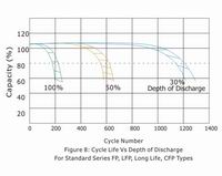
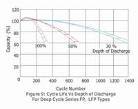
Giving due consideration to the above factors, the actual life of a battery in cycle service is dependent on the depth of discharge of each cycle. The greater the depth of discharge of each cycle, the less the number of cycles available from the battery.
B. Standby Life
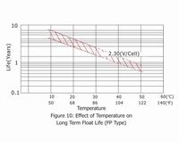
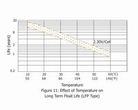
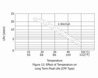
The estimated life under float service of Small type of General series is 7 years at 20℃/68°F; Medium type is 12 years at 20℃/68°F; Long life series is more than 20 years at 20℃/68°F. The float service life is affected by the factors listed above and the number of discharging, the depth of discharging the battery suffers during its life time. The more discharges suffered and the deeper the discharges, the shorter the battery life. The higher the temperature, the shorter the battery life. If the battery temperature remains at an elevated level for an extended period of time, the expected life is reduced by 50% for each 8 to 10℃ of constant temperature above 20℃/68°F.
5. Battery Storage
5.1 General Storage Conditions:
The battery should be stored under the following conditions.
(1) Low humidity
(2) 5 to 122°F(-15 to 50℃)
(3) Clean, and avoid direct sunlight.
5.2 Capacity after Long Term Storage
After long term storage, all batteries deliver less than rated capacity on first cycle. In cyclic application, full capacity may be obtained through several charge/discharge cycles, typically 2-3 cycles.
5.3 Refresh Charge
When batteries are placed in extended storage, it is recommended that they receive a refresh charge at recommended intervals as following;
Refresh charging method:
3 to 5 hours of constant current 0.1C Amps or 12 to 16 hours at constant voltage of 2.45V/cell
Storage Ambient: | Recommended Interval |
Below 20 ℃(68°F): | 12 months |
20 to 30℃(68 to 86°F): | 6 moths |
30 to 40℃(86 to 104°F): | 3 moths |
5.4 "Self Life"- typical capacity vs. time
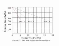
Self-discharge rate is very much dependent on the storage temperature as shown in Figure 13.Lower temperatures allow the battery to be stored for longer periods. (Each ten degree centigrade drop results in a halving of self-discharge rate and doubles storage time.)
5.5 "Self Life"-storage time vs. temperature
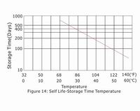
Figure 14 shows the time for the capacity to decrease to 50% of nominal capacity at each temperature during storage. If the storage temperature is known, the graph may be used for finding the most useful recommended refresh charge intervals.
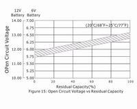
5.6 Open Circuit Voltage and Residual Capacity
Residual capacity can be estimated by measuring the open circuit voltage as shown in Figure 15.
5.7 Battery Internal Resistance
The internal resistance of a battery is lowest when the battery is in a fully charged state. The battery internal resistance will be increased gradually during discharge.Figure 16 shows the changing of internal resistance of KP12-7.2(12V7.2Ah) battery during different rated discharging
6.BATTERY DISPOSAL/RE-CYCLING
when a VRLA battery has reached the end-of-life it must be returned to the point of sale or to a licensed battery dealer for recycling.


